The thing I honestly miss most about my time studying and working abroad in Berlin is the nightlife. The clubs there are amazing and feature incredible music with equally amazing light shows.
I’ve always thought club lighting is cool and have wanted an excuse to play with DMX for some time. We love dancing too so a few weeks ago we decided to turn an empty room into our little private nightclub.
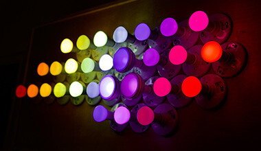
The colorful animated LED sign I made out of Hue bulbs was already in that room so the space already had a bit of a neon dance floor/nightclub feel.
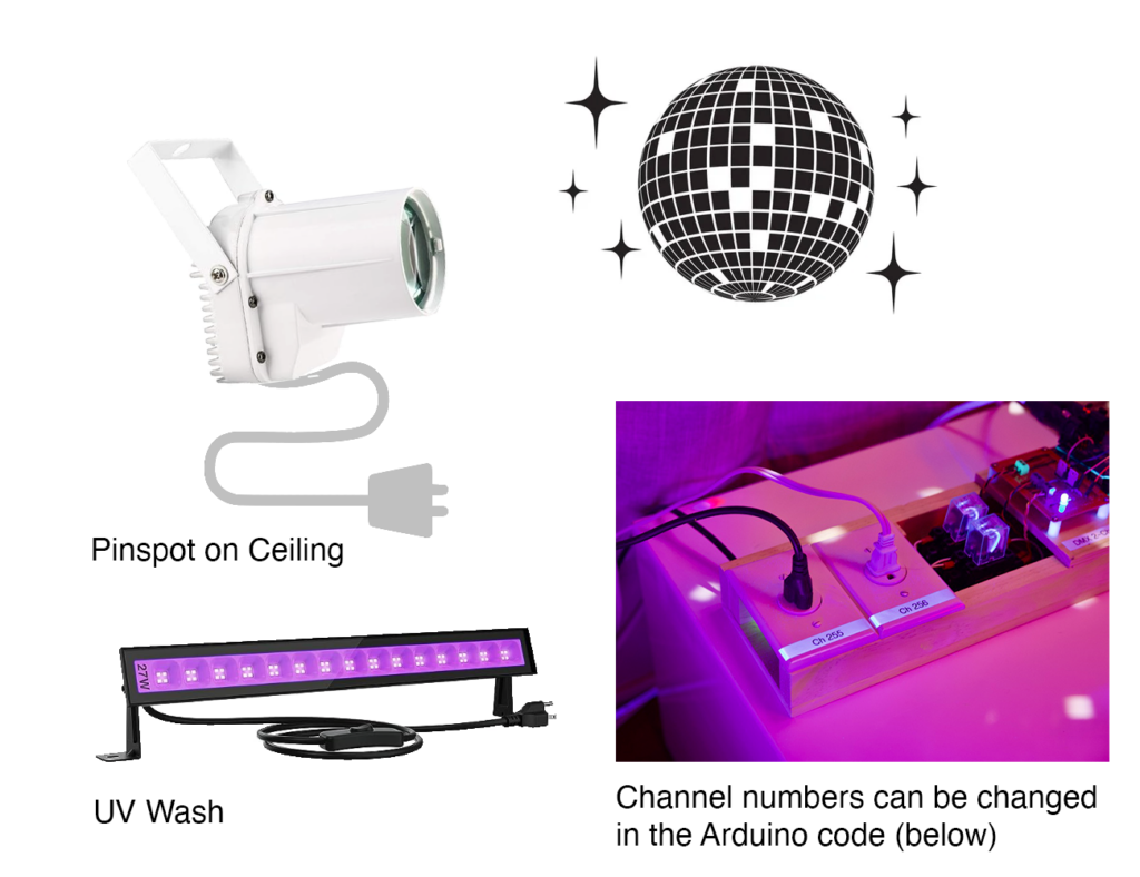
We bought two small DMX fixtures and two fixtures that did not have DMX: a small mirror ball light and a UV (Blacklight) flood light.
I needed a way to bring DMX control to 1) the mirror ball light and 2) the UV light so that they could remotely be switched on and off from the same software that controls the DMX fixtures.
Update: Read about the Art-Net to DMX Node I created to control my DMX lights wirelessly
🎯 Design Goals
- Two switched (DMX-controlled) outlets for controlling basic on/off lighting fixtures that don’t support DMX
- A simple design (no custom PCB)
- DMX In & Out
- Using an old Arduino Uno Rev3
Illustration
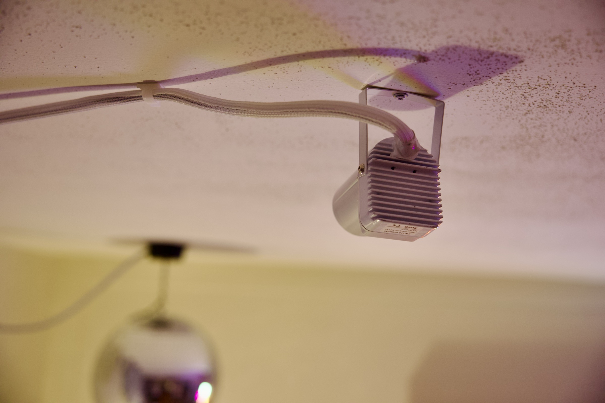
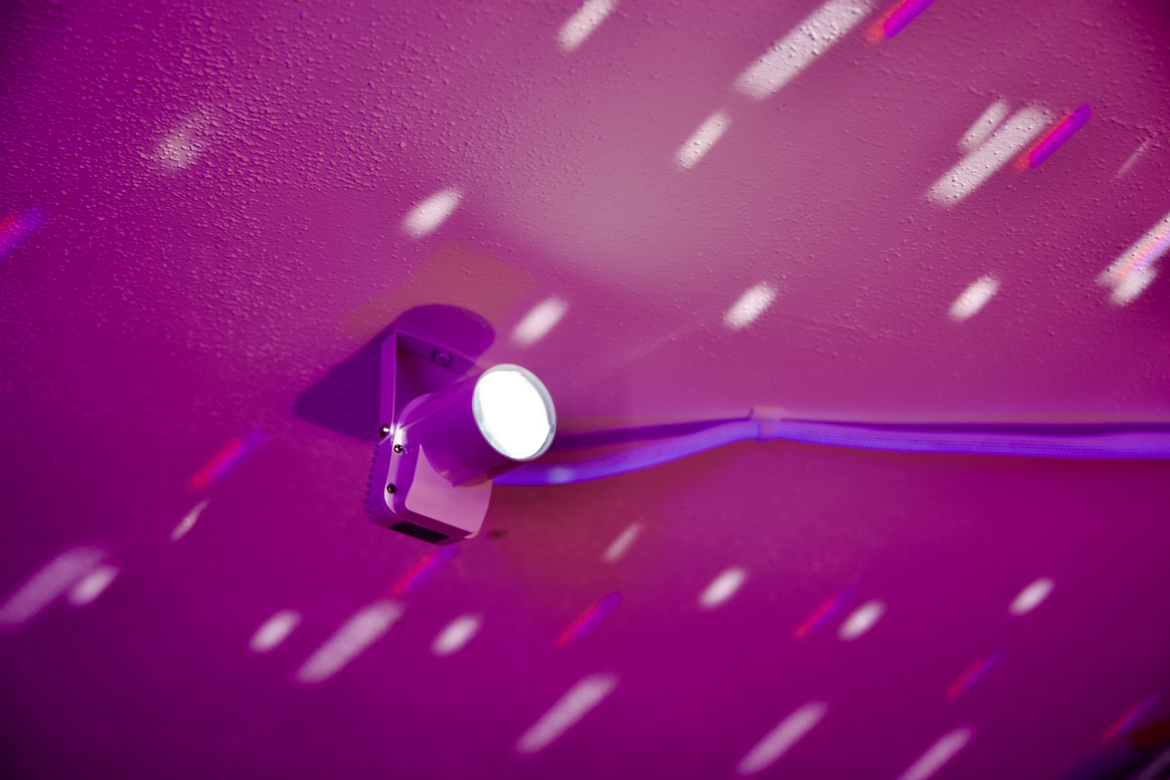
I want to be able to use DMX to turn on/off a UV Wash and a white pinspot pointed at a mirror ball. The design I settled on resembles a 2-outlet power strip:
🛒 Materials
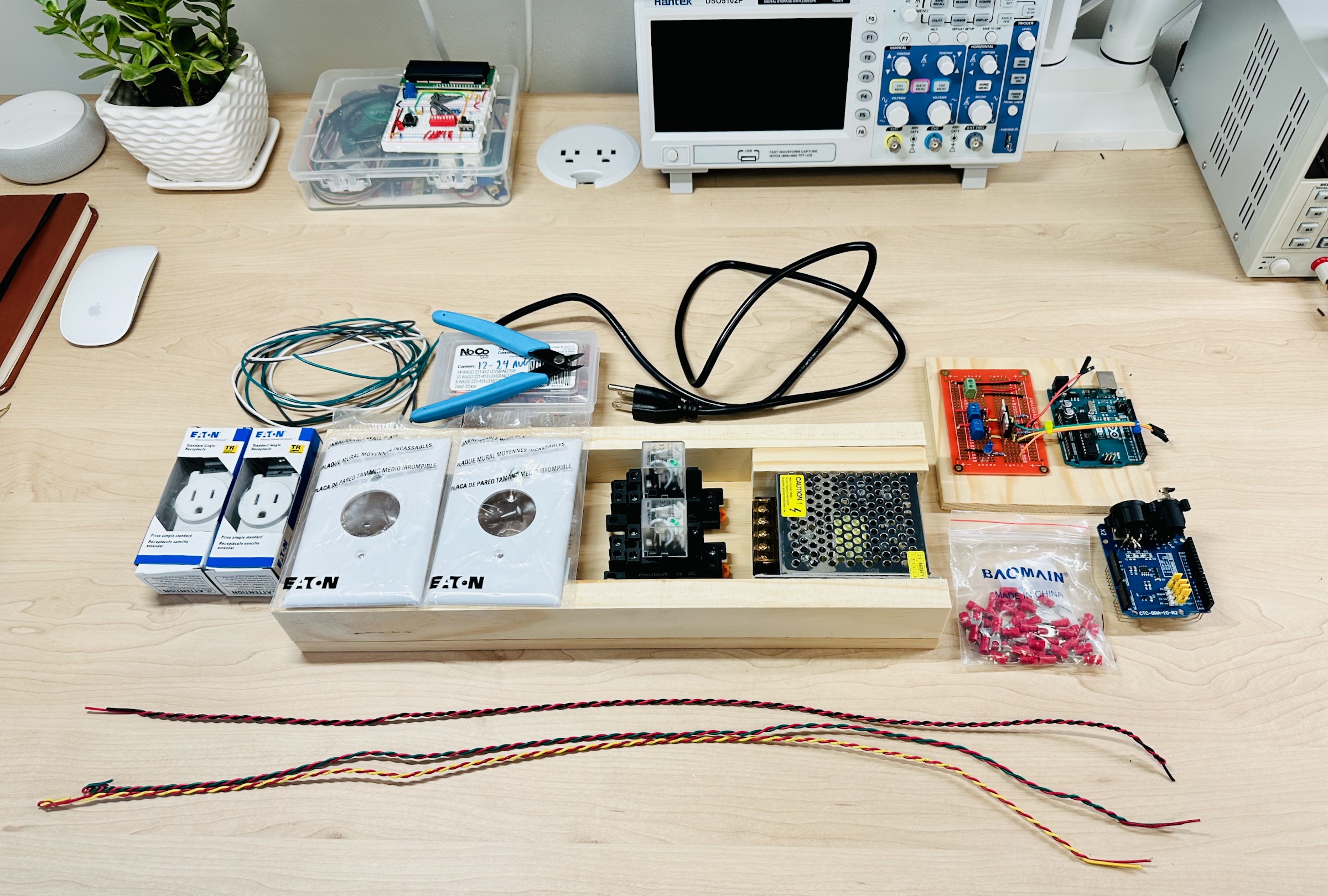
- Arduino UNO REV3
- CQRobot DMX Shield
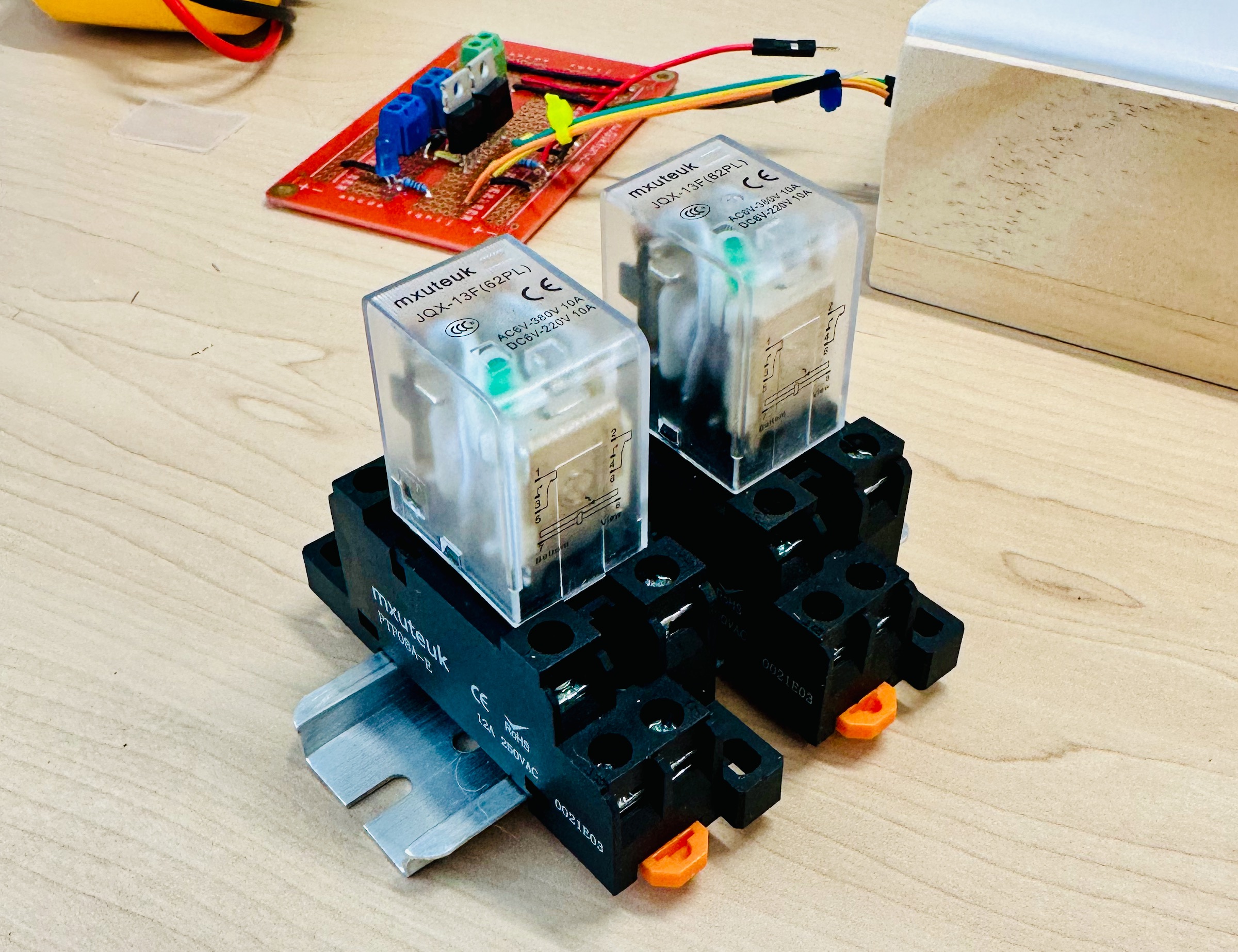
- 2 Relays with DIN Rail
- Blue LED (You can use a different color but should adjust the current-limiting resistor)
- Prototyping Board (Soldering Required) or a Breadboard
- 3x PCB Screw Terminals
- 2x Logic Level N-Channel Mosfets
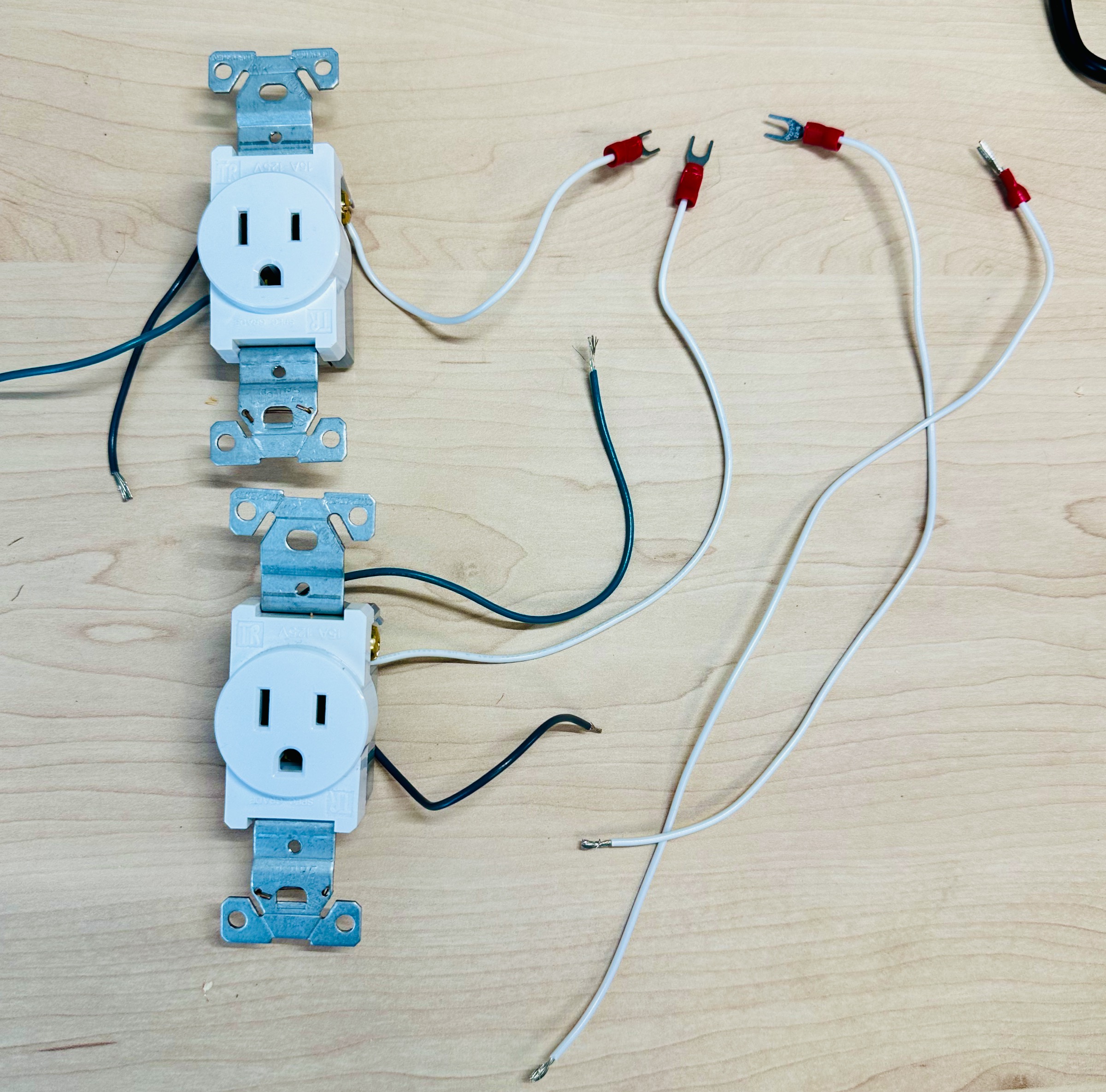
- 2x Single Receptacle Power Outlets (I bought mine at Home Depot)
- 12V Power Supply
- Breadboard/Jumper wires
- 18 AWG Wire
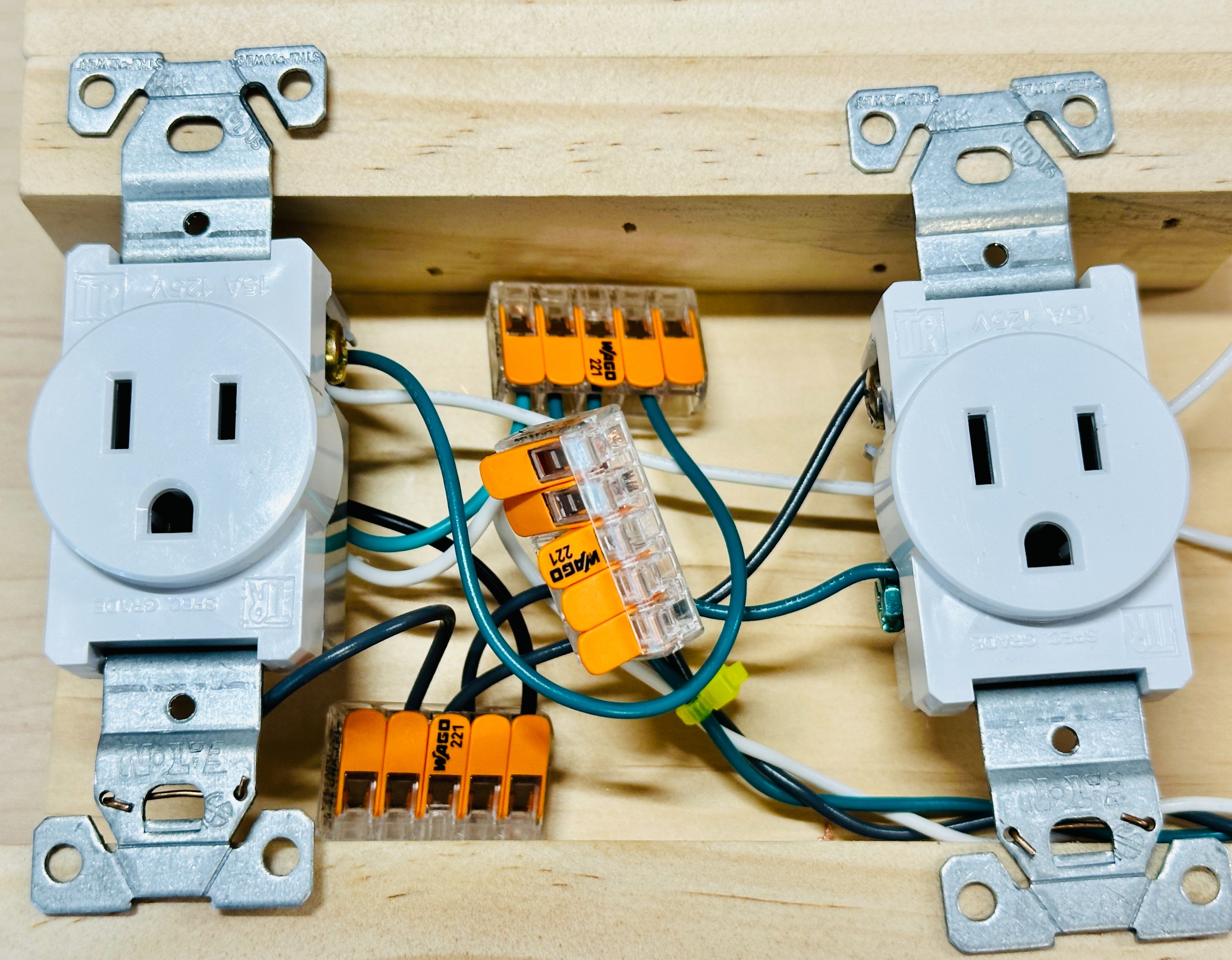
- Wago Lever-Nuts (5-port)
- Computer power cord
- ~100 Ohm Resistor
- 2x 1 kOhm Resistors
- 2x 1N4007 Diodes
- Scrap Wood & Fasteners
🛠️ Tools
- Multimeter
- Soldering Iron (If using a perf board)
- Saw to cut wood
- Something to strip wires (Scissors, Wire Stripper Tool, etc!)
- Drill or Impact Driver
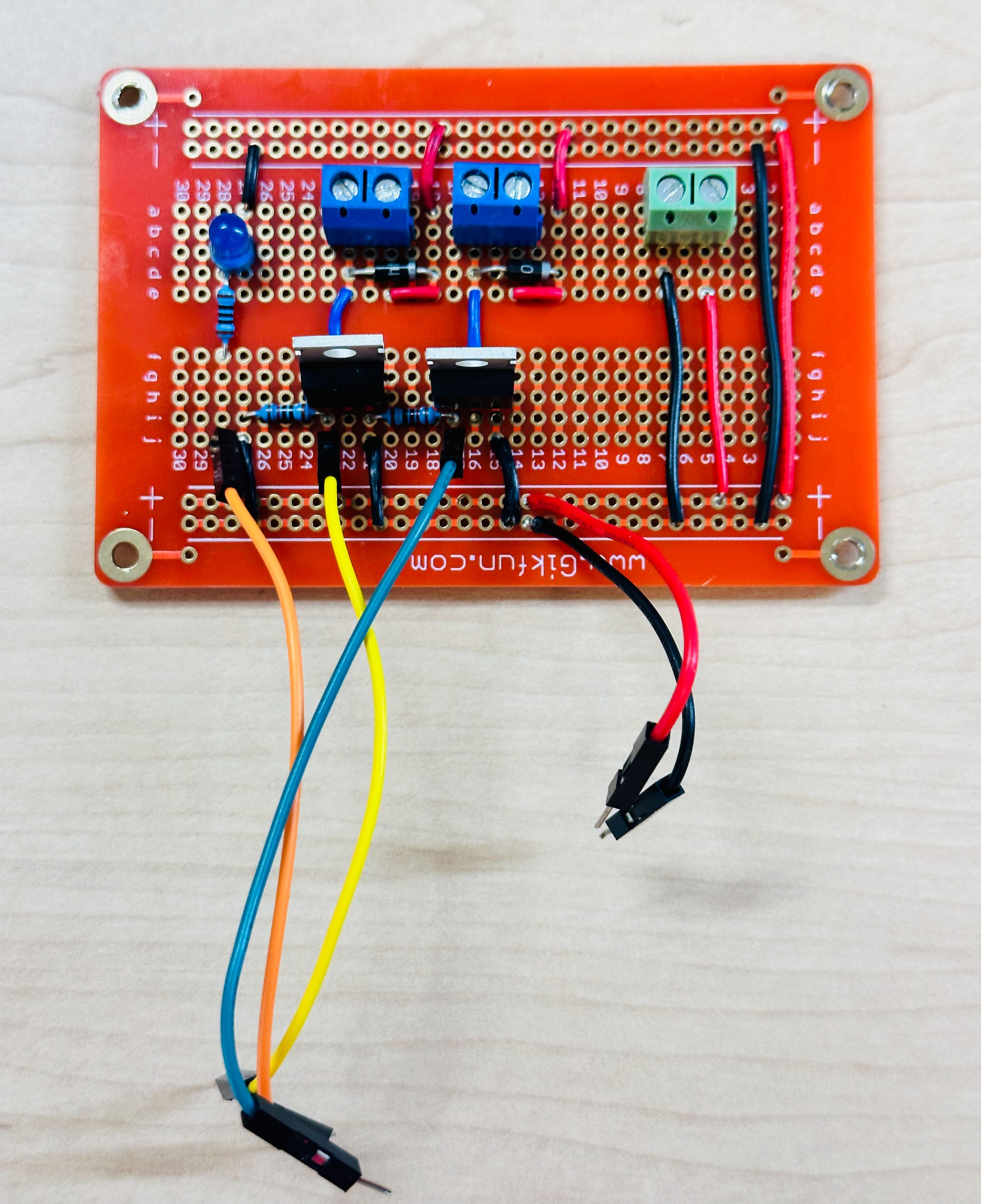
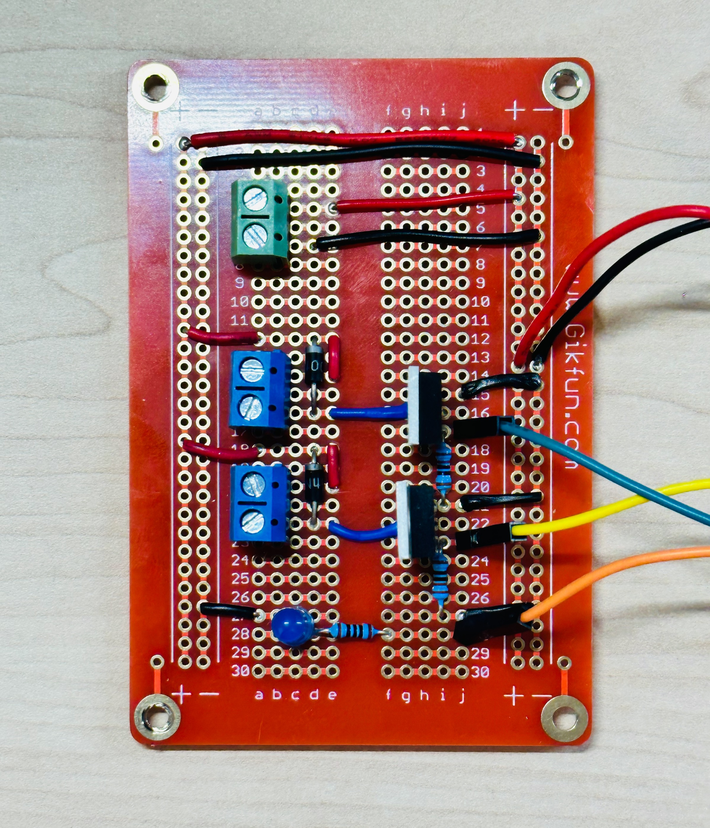
Circuit Design
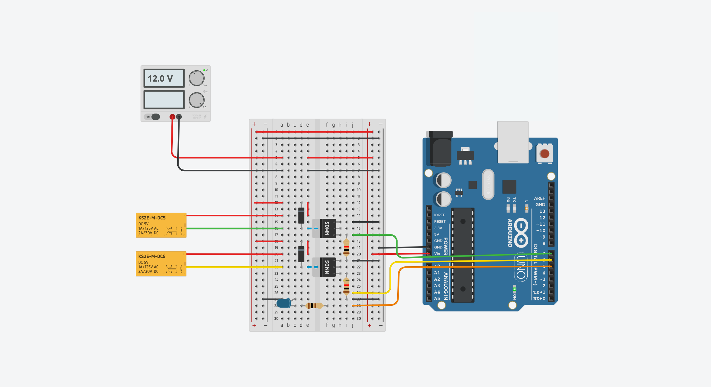
The circuit is very simple and is easy to solder on a protoboard or put together on a breadboard. It has two mosfets that turn on/off two 12V relays. The relays switch the power to the two outlets.
The DMX Shield is then installed on top of the Arduino.
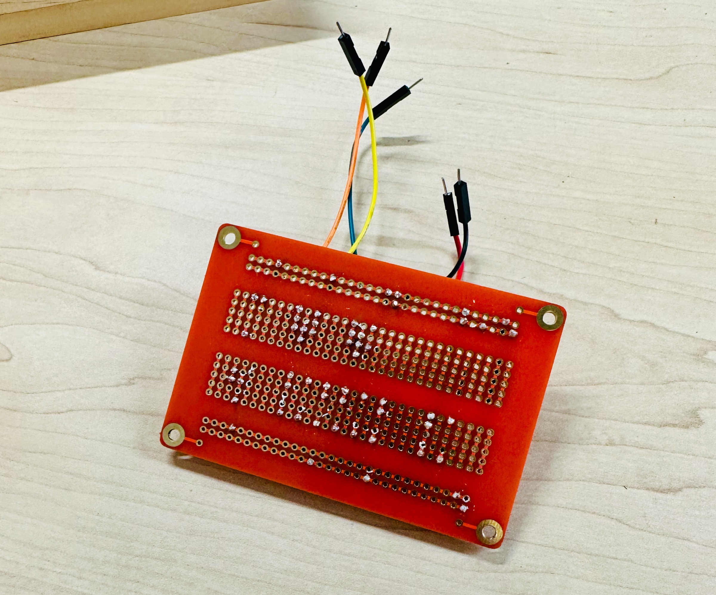
Soldering The Circuit Board
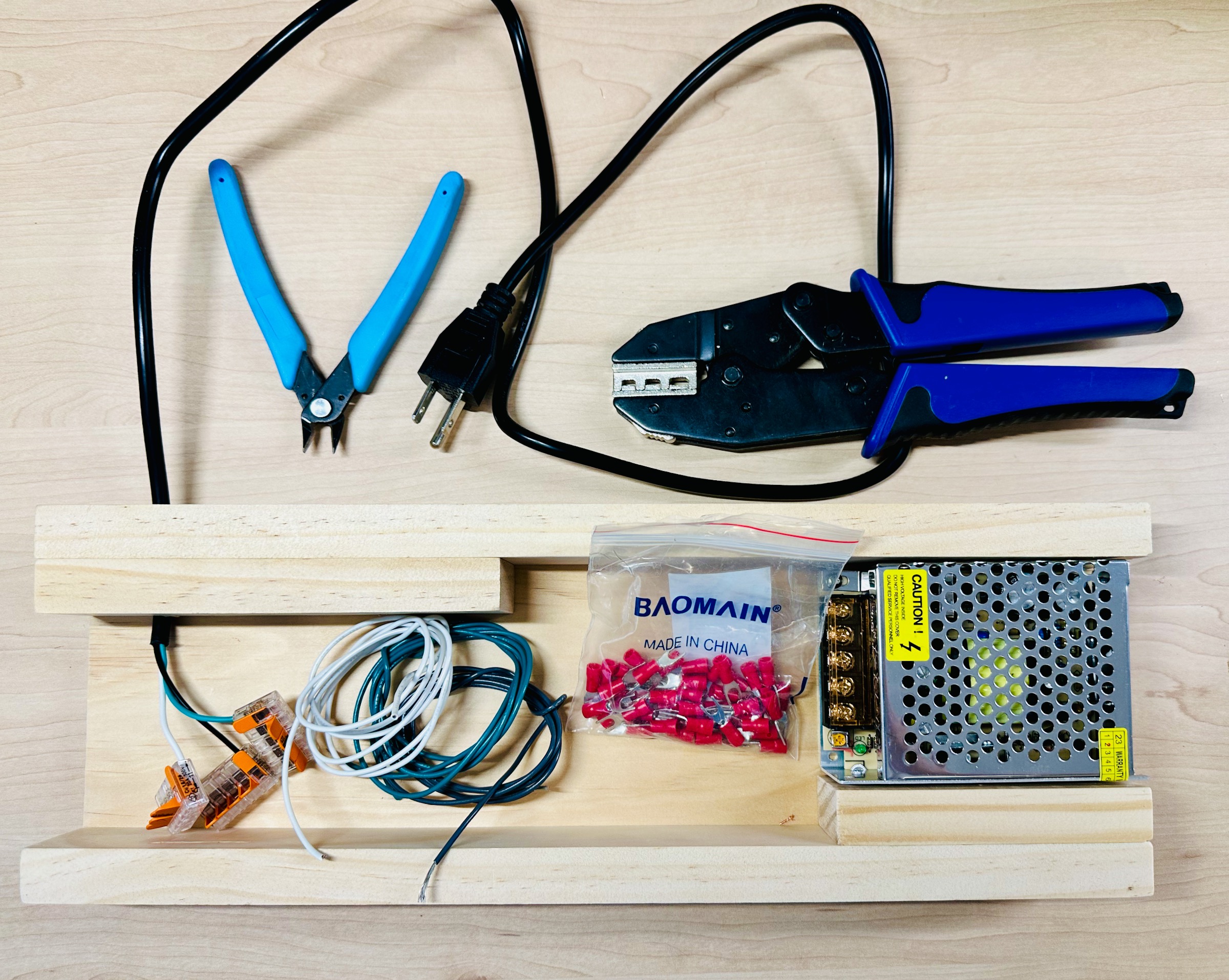
Build the Enclosure
I designed an enclosure using some scrap wood I had around. Feel free to be creative!
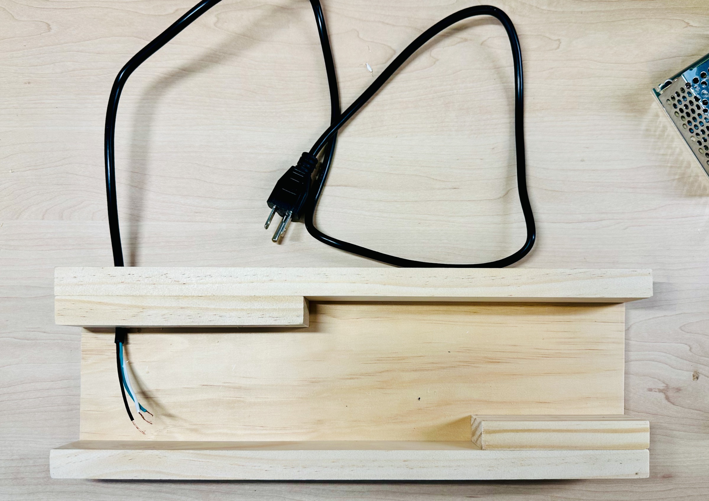
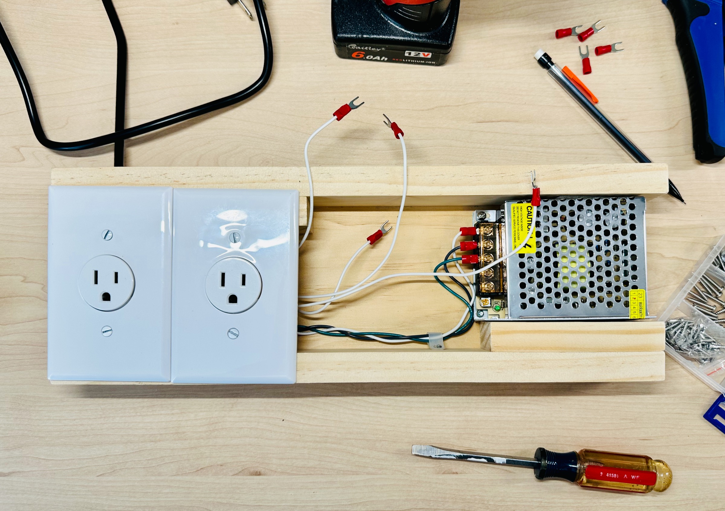
Wiring the 12V Power Supply
Working with mains voltage (120V) is dangerous. Be careful.
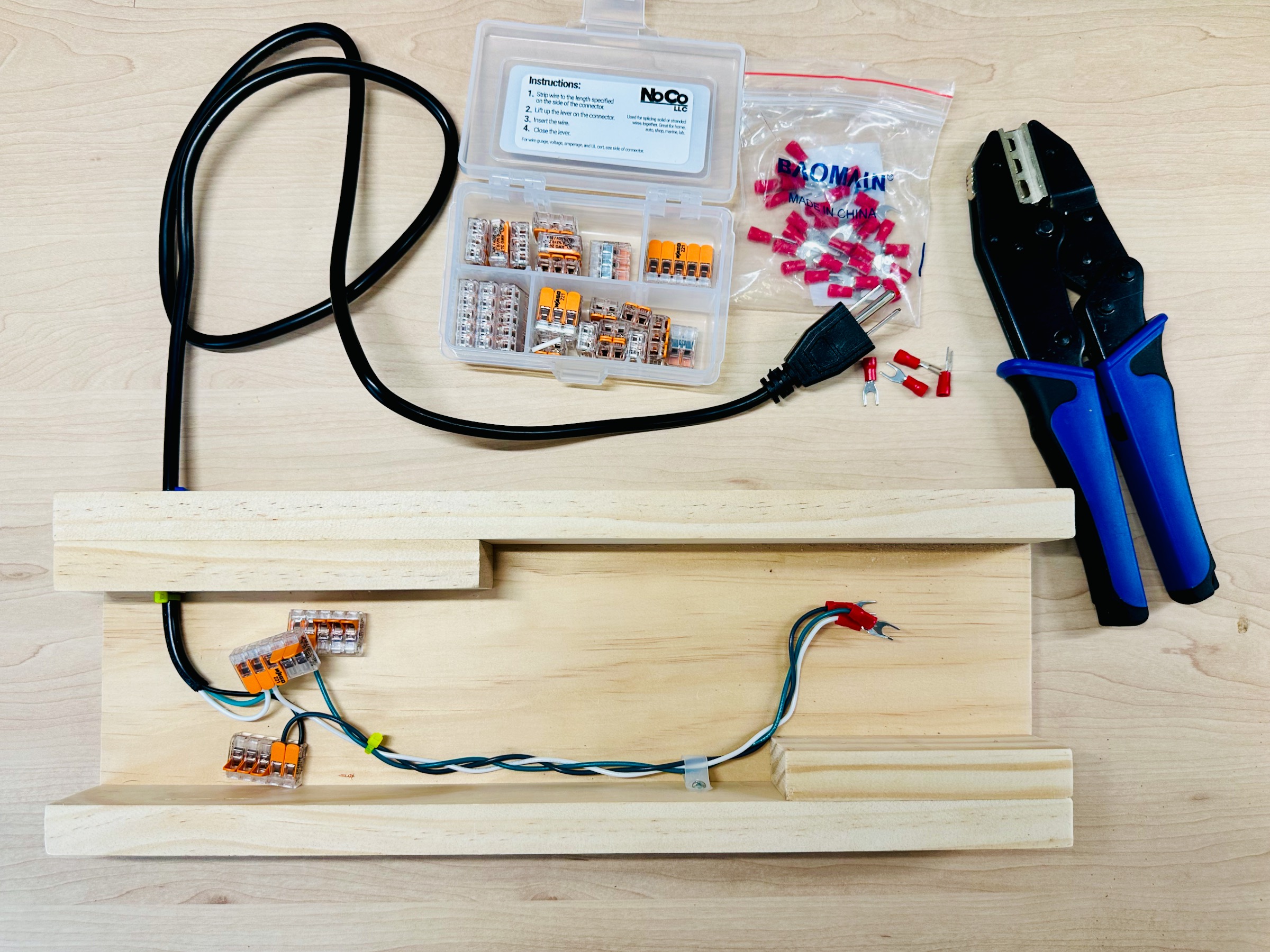
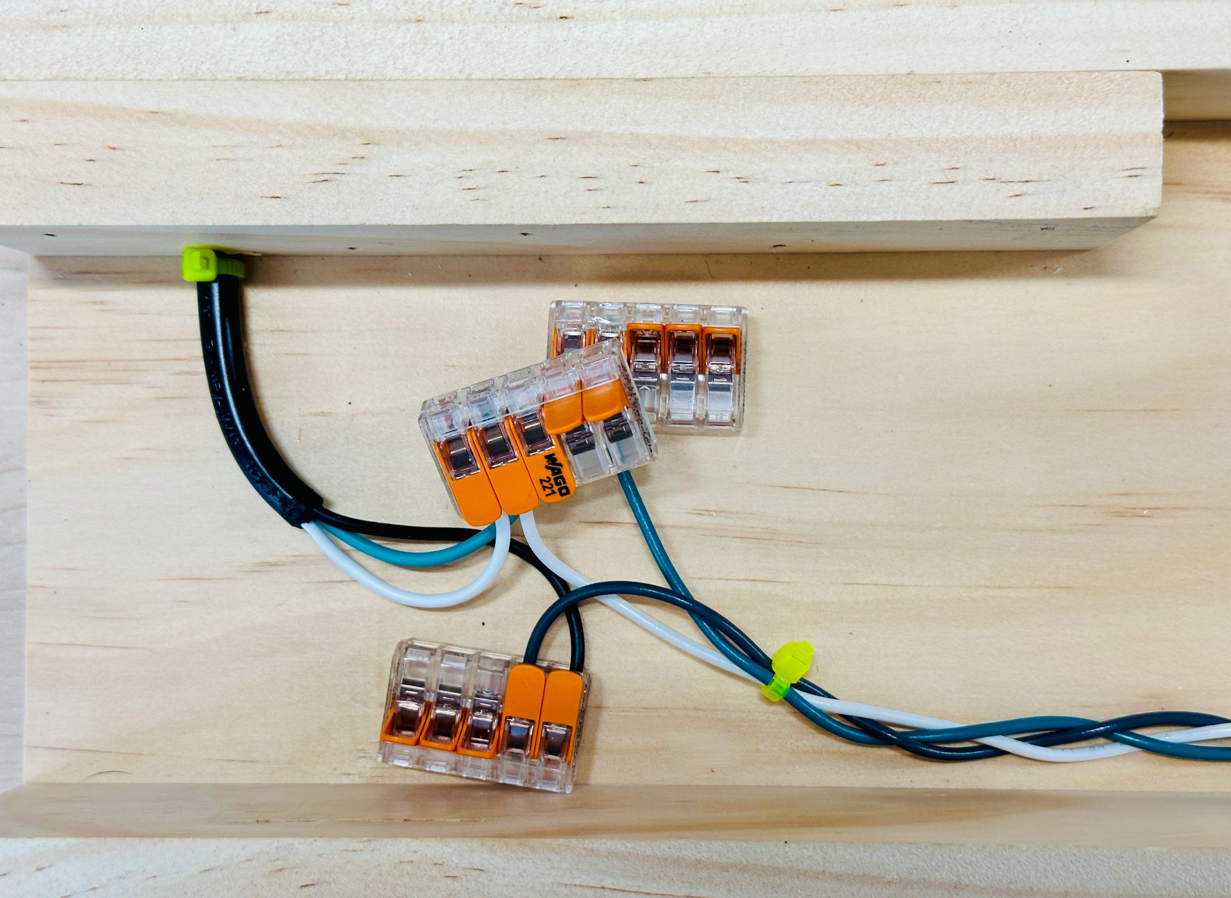
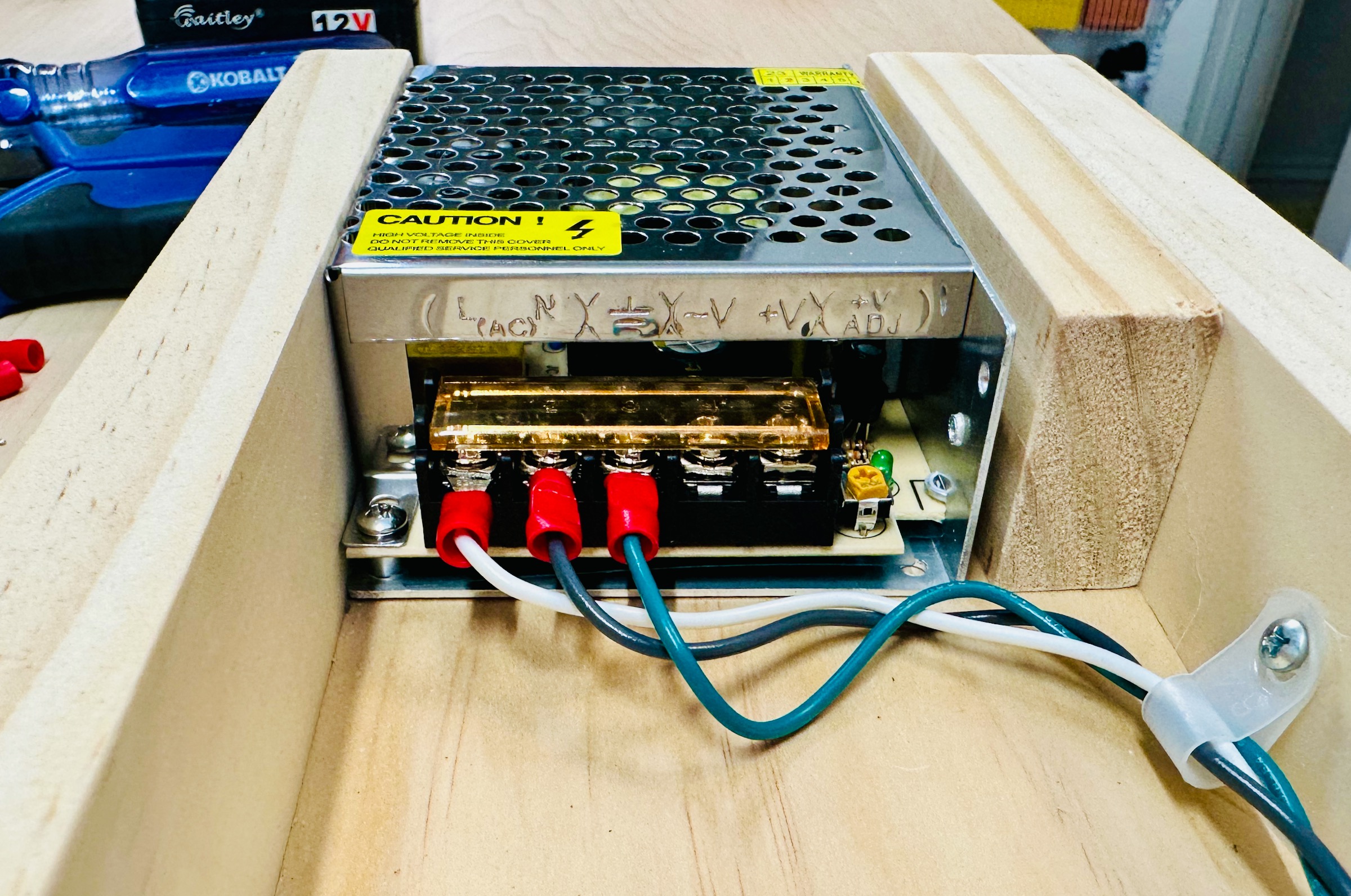
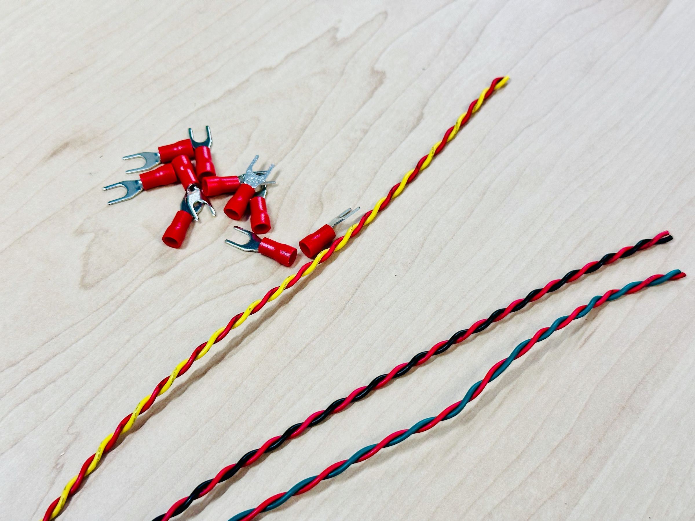
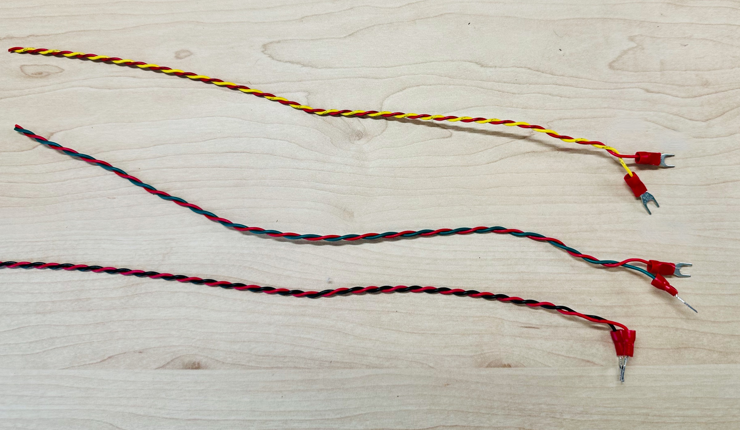
Connect the hot (black/dark gray) wire from the wall to each socket’s hot terminal.
The neutral wire coming in from the wall will be connected to both relays before being connected (through the relay) to the socket. When the relay is switched on the current will be able to flow through whatever light is plugged into the socket.
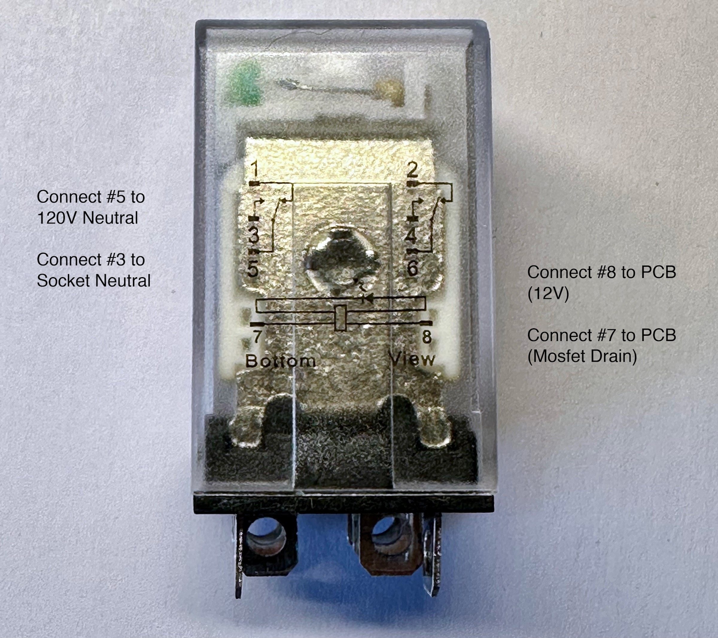
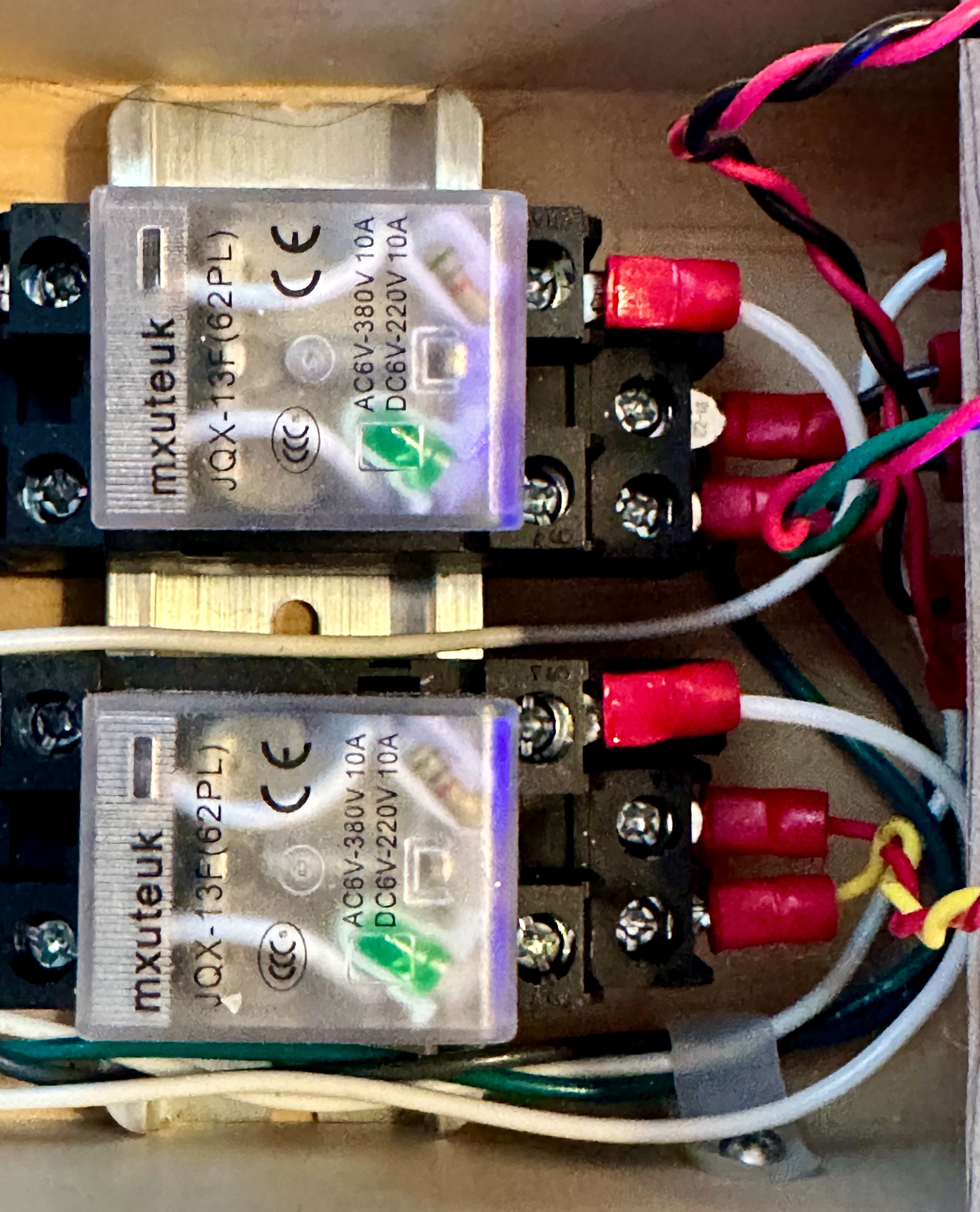
Wiring the Relays

Connect the neutral leads (from socket and mains power) to relay pins #5 and #3. This way no current will flow unless the relay is energized.
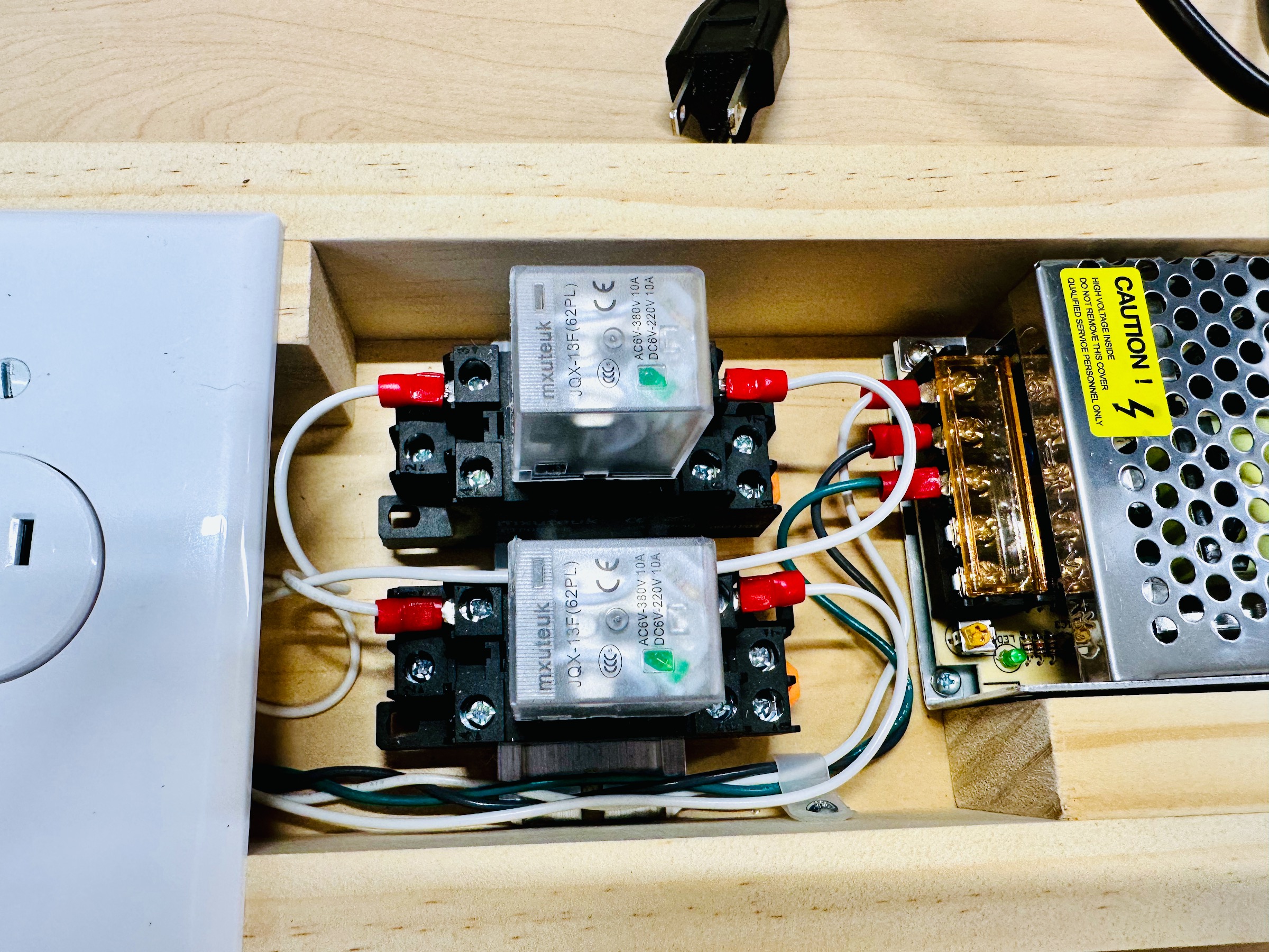
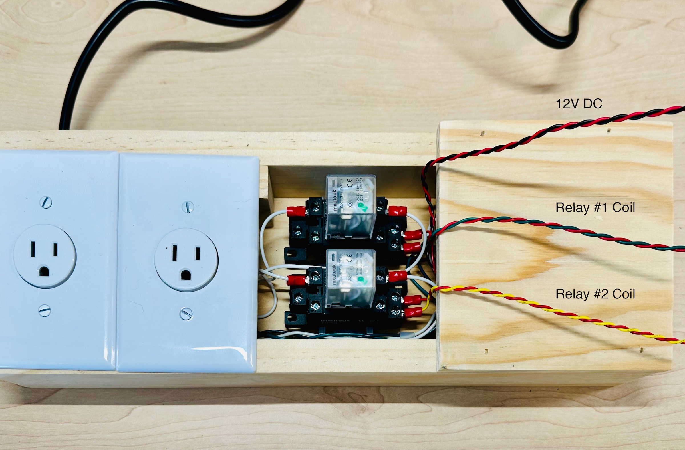
Next, we need to connect the relay coils to the mosfet circuits on the PCB. We’ll also run the 12V power output up to where the PCB and Arduino will be located (Above the power supply)
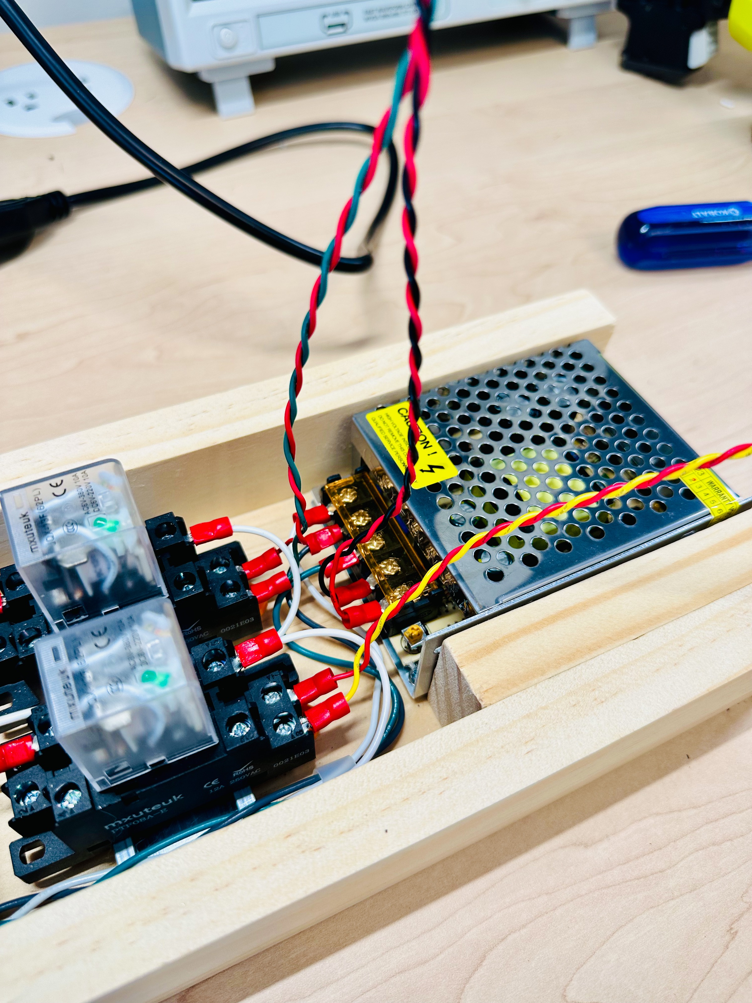
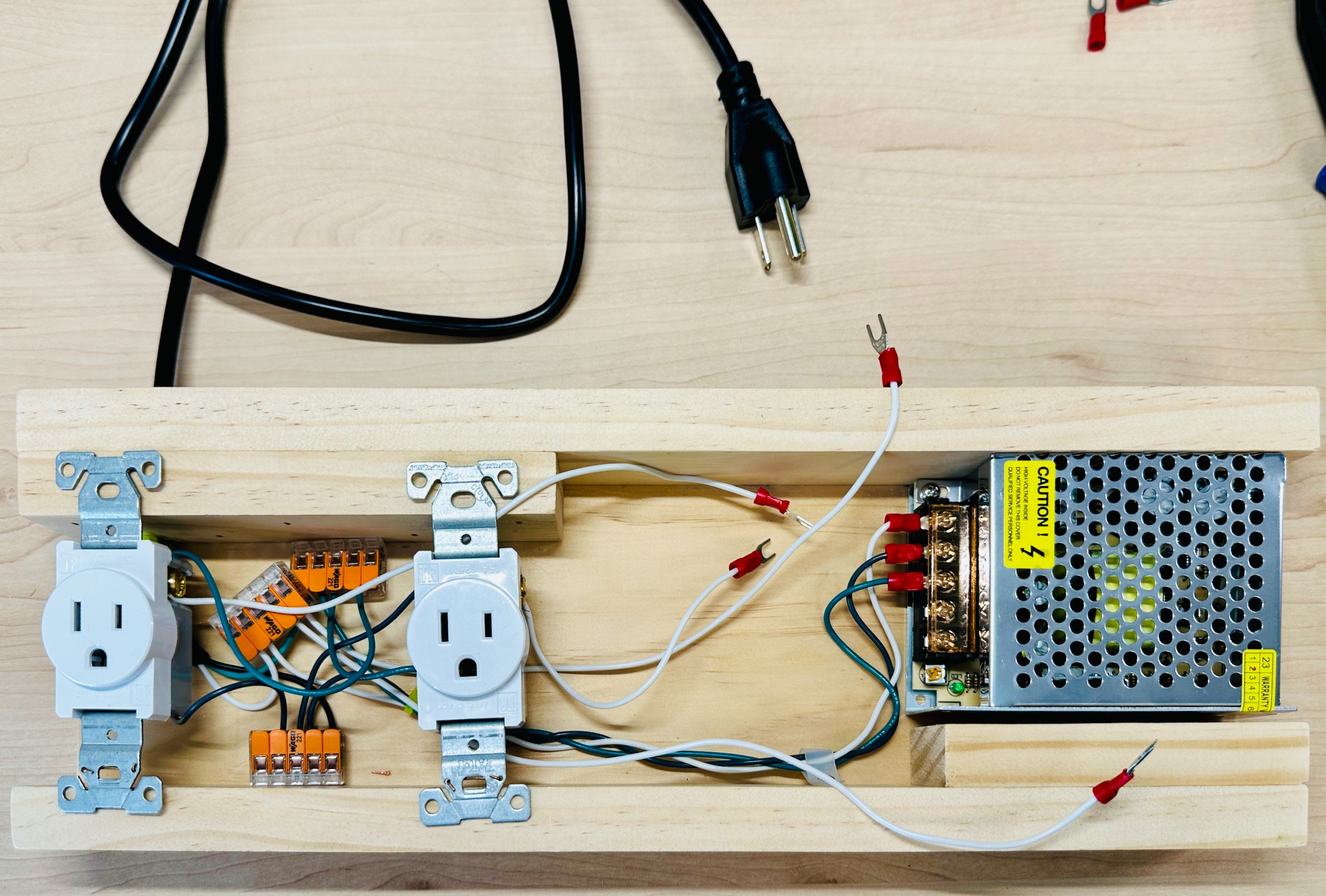
I added a piece of wood above the power supply for mounting the Arduino on top of. It should now look like the following:
Finally, mount the PCB and Arduino securely and connect the power supply and relays to the screw terminals.
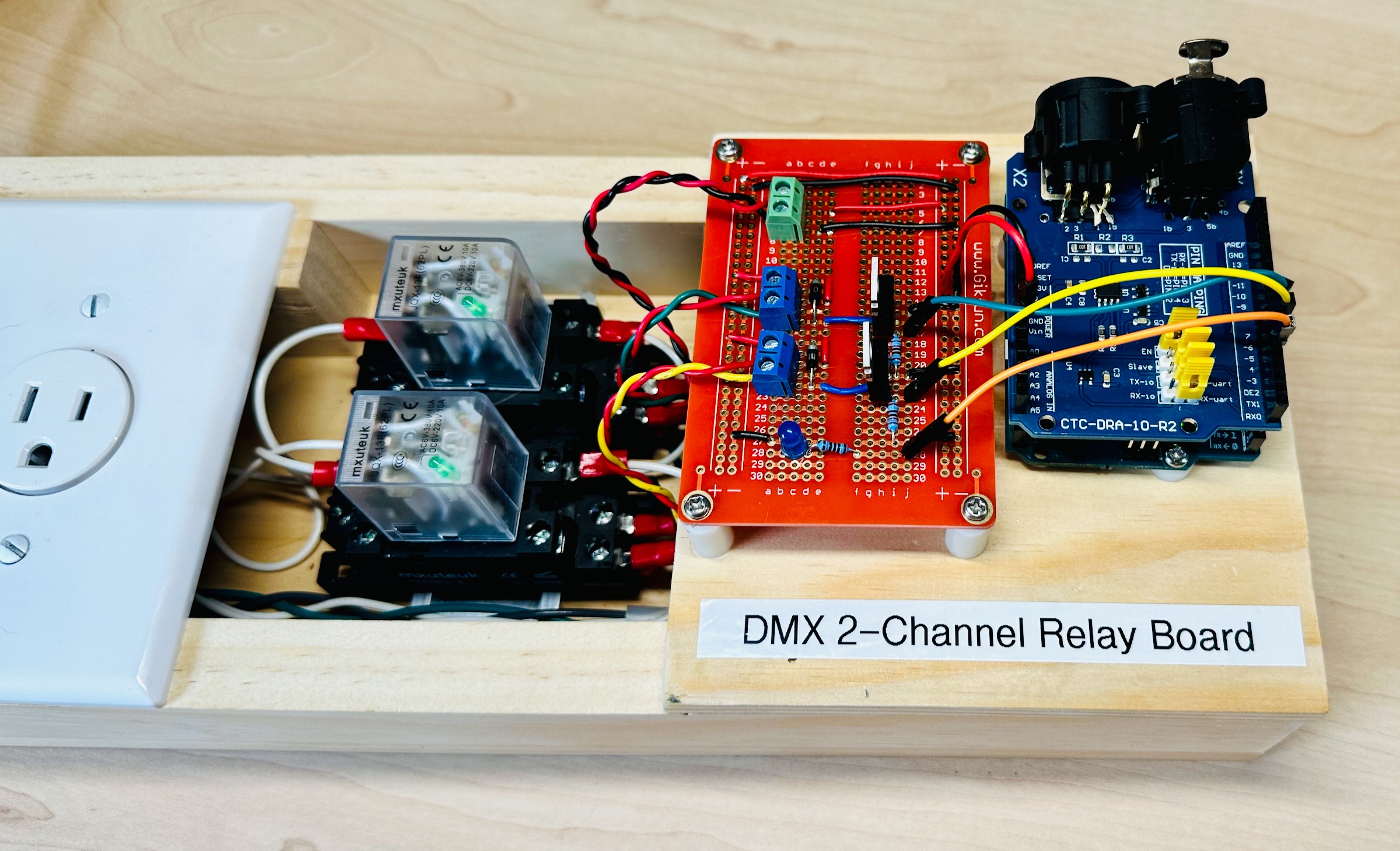
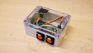
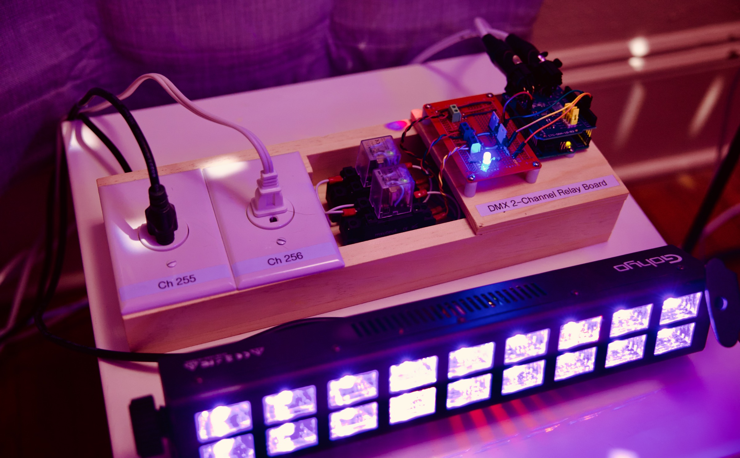
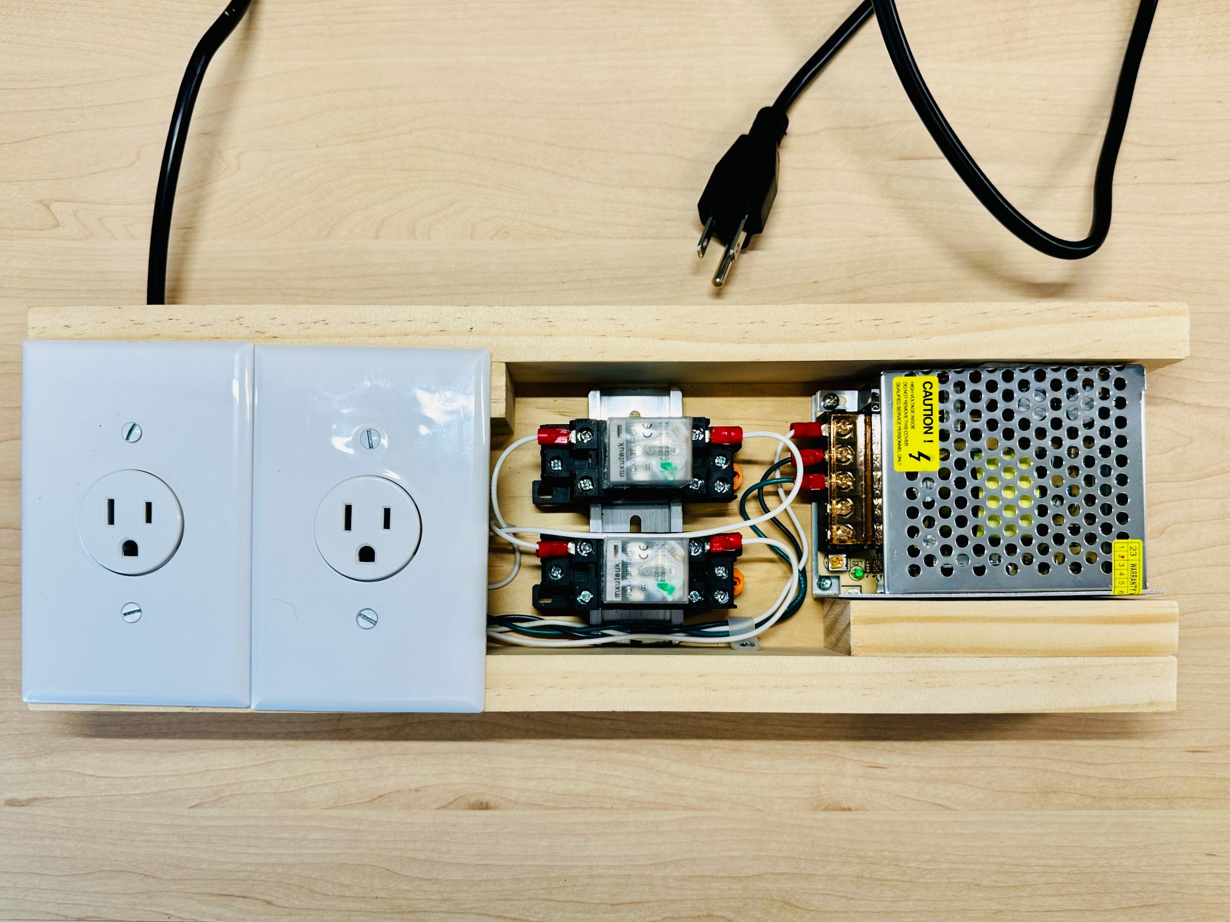
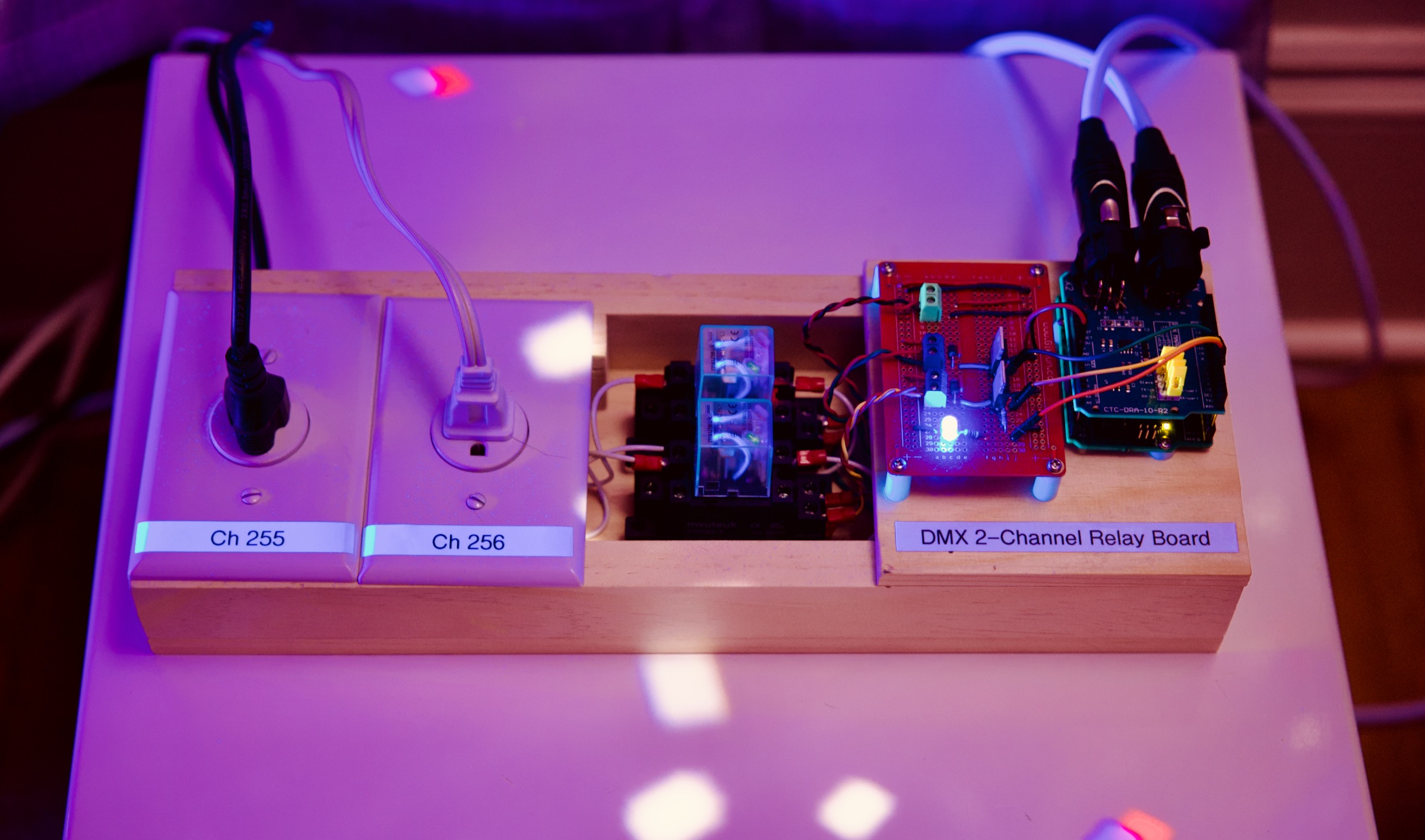
The Finished Hardware
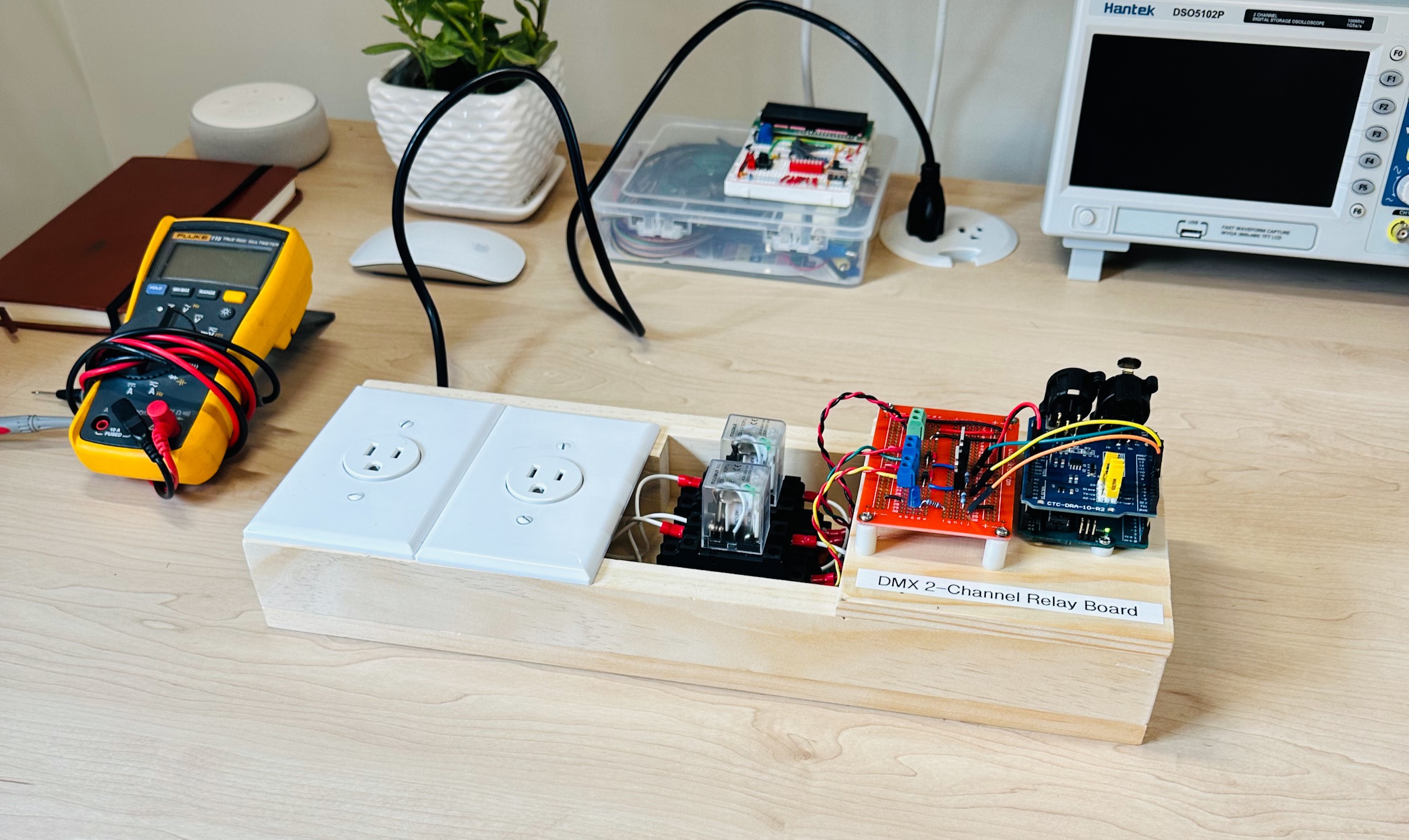
Now we just need to program the Arduino and we’re done!
Arduino Code
Below is the code that listens for DMX messages on two channels (one for each relay). DMX channels can be set to a value from 0 to 255. I choose to have the relays turn on if the value for the associated channel is greater than 0. You can choose a different threshold if you’d like.
/*

 DMX 2-Channel Relay Board
 DmxRelayBoard.ino

 Note: Requires library DMXSerial by Matthias Hertel.
       Tested using version 1.5.3.

 - Starting Channel (Configured below): 255
 - Relays turn on if data value is larger than 0 (1-255)
 - Blue status LED indicates that DMX frames are being received

 Created 08/11/2023 by Taylor Mingos

*/

#include <DMXSerial.h>

const int START_CHANNEL = 255;
const int RELAY_1_PIN   = 7;
const int RELAY_2_PIN   = 6;
const int STATUS_LED    = 5;

void setup() {
  pinMode(RELAY_1_PIN, OUTPUT);
  pinMode(RELAY_2_PIN, OUTPUT);
  pinMode(STATUS_LED, OUTPUT);

  DMXSerial.init(DMXReceiver);
}

void loop() {
  unsigned long lastPacket = DMXSerial.noDataSince();

  if (lastPacket < 1000) {
    digitalWrite(STATUS_LED, HIGH);
    digitalWrite(RELAY_1_PIN, DMXSerial.read(START_CHANNEL) > 0);
    digitalWrite(RELAY_2_PIN, DMXSerial.read(START_CHANNEL + 1) > 0);
  } else {
    digitalWrite(STATUS_LED, LOW);
  }

  delay(10);
}
Note: The DMXSerial library requires that you configure the DMX shield to use the UART pins, like so:
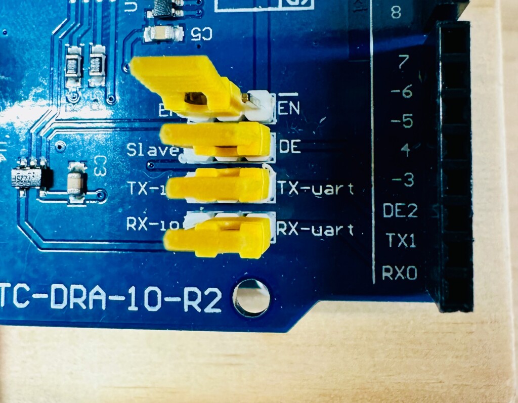
If you have trouble flashing the Arduino you may need to remove the DMX shield or at least remove the top jumper (en) to temporarily disable the DMX shield. This is because the Arduino is flashed over the UART Tx & Rx pins, the same pins the DMX shield listens to.
🪩 All Done!
Enjoy! 🕺